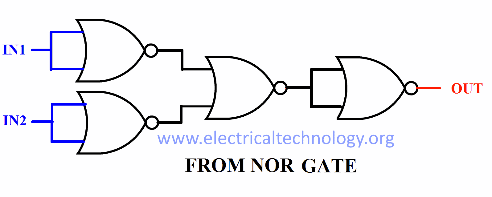
Implementation of AND Gate from NOR Gate. An AND Gate is a basic logic gate that performs the binary multiplication, i.e., it gives a HIGH or Logic 1 output, only when all its inputs are in HIGH or Logic 1 state. On the other hand, a NOR gate is a type of universal logic gate. Therefore, NOR gate can be used to realize any other type of logic gate.. In a circuit, logic gates work based on a combination of digital signals coming from its inputs. Most logic gates have two inputs and one output, and they are based on Boolean algebra. At any given moment, every terminal is in one of the two binary conditions: true or false. False represents 0, and true represents 1.
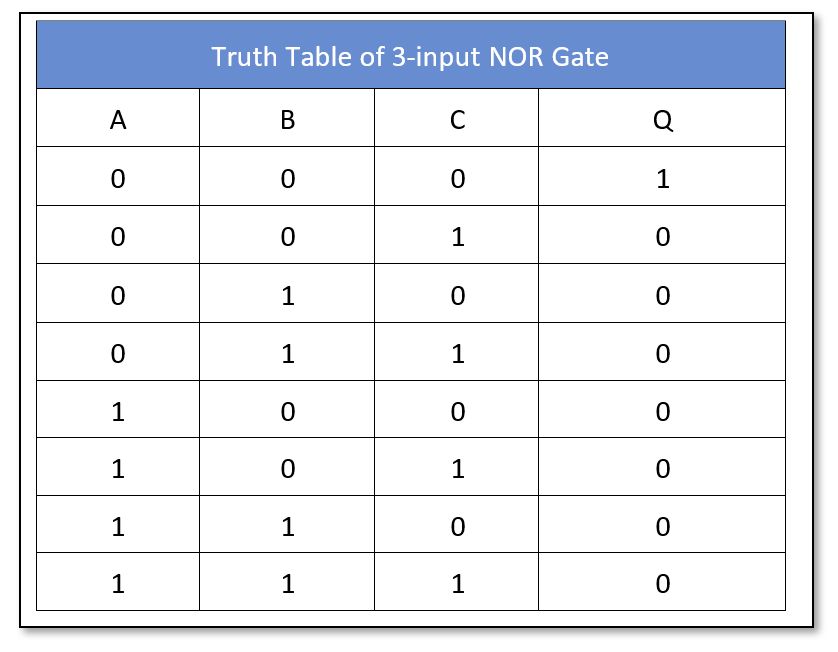
Logic NOR Gate
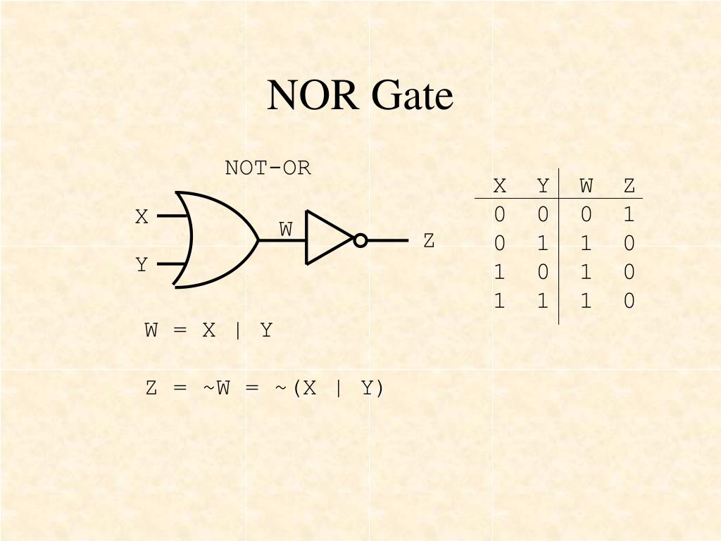
PPT Basic Logic Gates and De Theorem PowerPoint Presentation ID2951035
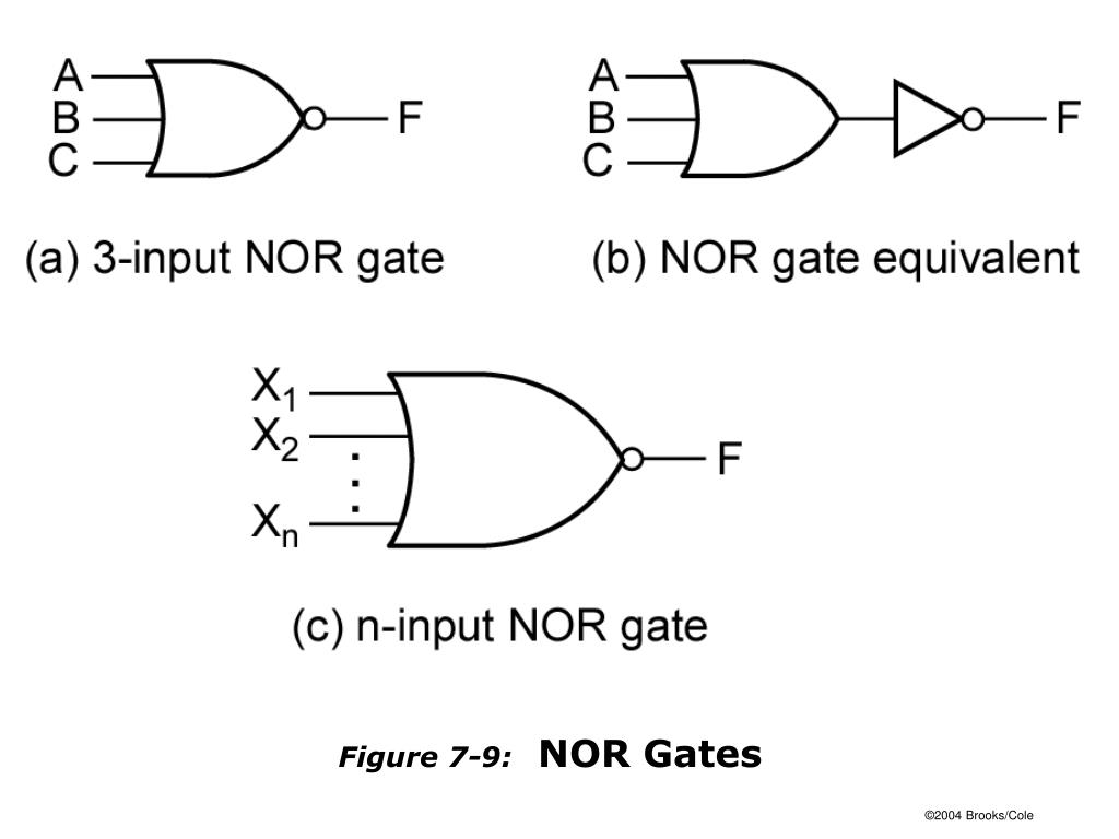
PPT FIGURES FOR CHAPTER 7 MULTILEVEL GATE CIRCUITS NAND AND NOR GATES PowerPoint Presentation
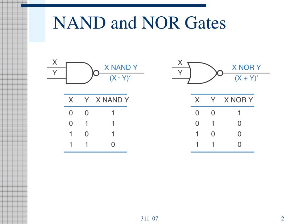
PPT NAND and NOR Gates PowerPoint Presentation, free download ID4401548

NOR GATE AS UNIVERSAL LOGIC GATE AND,NANDPART2 YouTube
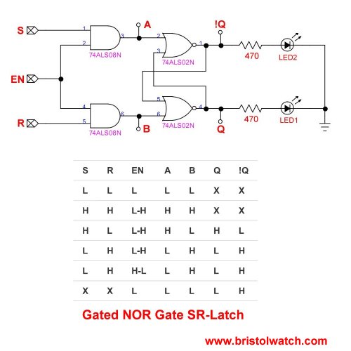
Tutorial NOR Gate SR Latch Circuit

NOT Gate, NOR Gate, NAND Gate with Bilingual explanations & class notes YouTube
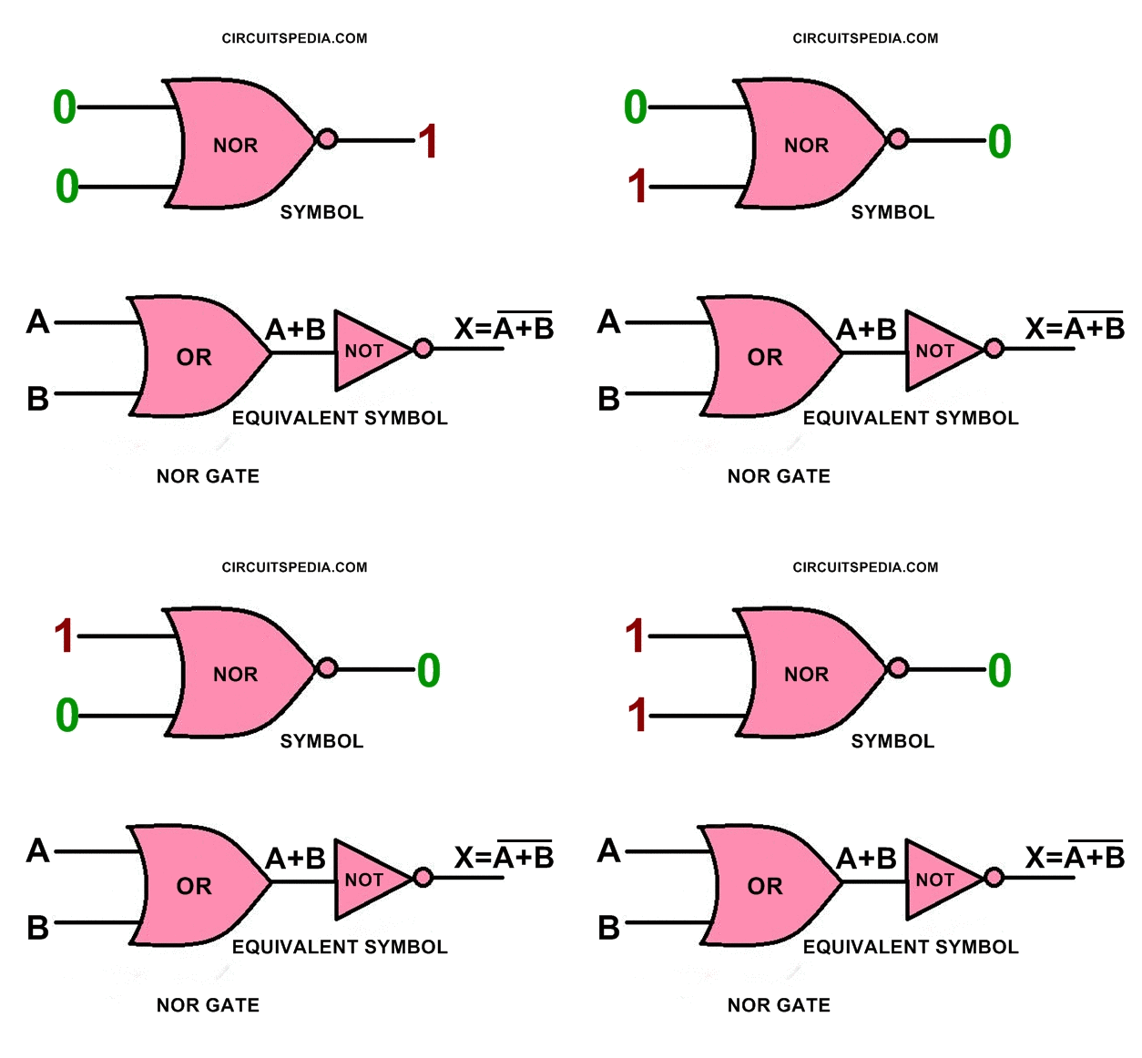
logic gates circuit Theory articles Community

Logic NOR Gate Tutorial Earth Bondhon
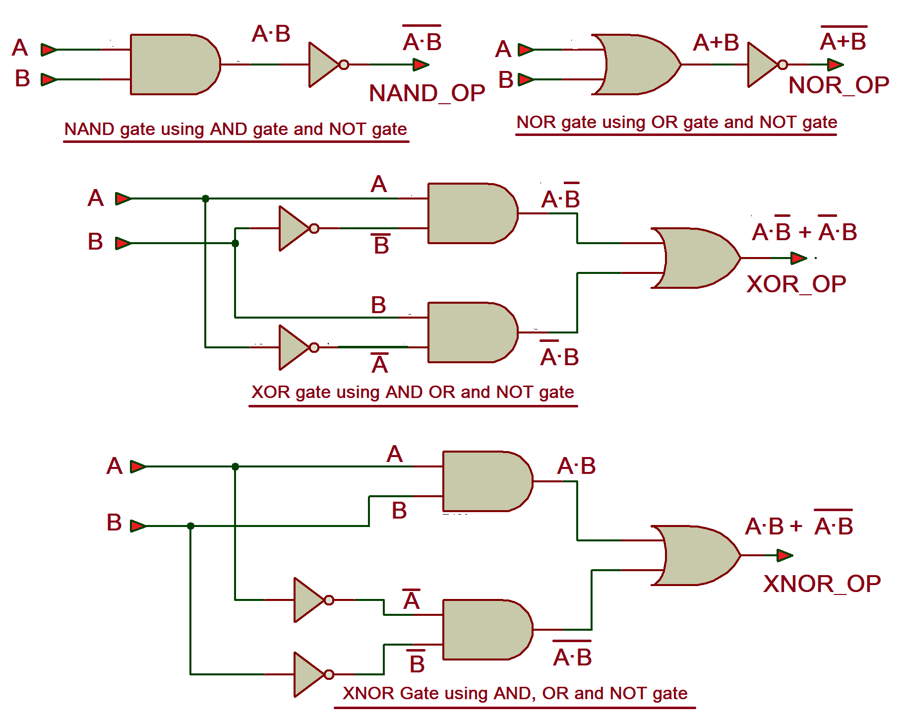
VHDL Tutorial 5 Design, simulate and verify NAND, NOR, XOR and XNOR gates using ANDORNOT
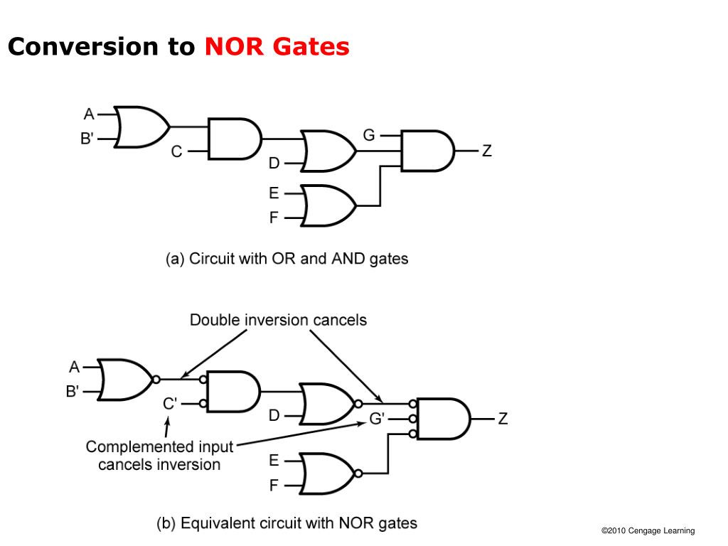
PPT SLIDES FOR CHAPTER 7 MULTILEVEL GATE CIRCUITS NAND AND NOR GATES PowerPoint Presentation
Digital Logic NAND Gate Universal Gate Electrical Technology

EXOR Gate using NOR Gate Circuit Analysis Electrical Engineering YouTube
PPT Chapter 3 Describing Logic Circuits PowerPoint Presentation, free download ID7042267

Universal Logic Gates and Complete Sets
VHDL Tutorial 8 NOR gate as a universal gate

PPT Unit 7 MultiLevel Gate Circuits / NAND and NOR Gates PowerPoint Presentation ID4974300

Logic Gates using NAND and NOR universal gates

Introduction to NOR Gate projectiot123 Technology Information Website worldwide

NOR Gate Logic Gates Tutorial
3. OR Gate: OR gate is another basic logic gate like AND gate it as two input and one output. The operation of gate is such that output of gate is binary 1 if any of the input is binary low and we will receive logic zero only when both the inputs are low. Truth table of OR gate are as follows-. Number of stage possible = 2 n =2 2 = 4.. As in each of the first three cases, a full AND (which would be true and true) isn't present. Hence, the outcome is true ( 1 ). For the last input, true and true, a full AND is present and thus (due to the NOT component, the N in NAND ), the outcome is false. In this image, we see an SN7400N chip that has four logic gates, namely, NAND gates.